
Printmaking is a private interest of mineand recently I have been feeling the need to leap back to silkscreening t-shirts and art prints. Light-sensitive emulsions can be used fairly frequently across fine art printmaking and photography methods, and if you’ve ever created your own PCB, then you may have employed a UV-sensitive resist to etch the circuit. Cyanotypes (aka blueprints) have been employed both by artists and draftsmen, and can readily be subjected in direct sun for those who have that available. Otherwise, you may want to construct a UV lightbox!
Even the lightbox itself is made from a huge poster framework, some scrap wood, plus a few UV-LED tape. To construct the boxI cut a few scrap plywood to approximately 2.5 inches in diameter, and used wood screws and glue to adhere to the walls of this box into your fiberboard backing board of this poster framework.

When the glue was dry, I cut on my LED tape to lengthwise strips and then taped them in to position, and then soldered jumper wires to connect up everything. Eventually I drilled out a hole slightly bigger than the LED tape included socket jack connector, along with”mounted” it at the face of the box using a massive glob of hot glue. After testing my circuit, then I put the clear plastic and black frame in addition to the box, also inserted a few rubber feet into the bottom to prevent scratching surfaces, thereby finishing the true lightbox part of this undertaking. The plastic is glued to the dark poster framework, and it is quite flimsy, but it should do the trick before I can discover some more straightforward plexiglass to substitute it. This lightbox can be used standalone with no MicroMod timer simply by plugging in the enclosed wall wart and linking the pins.
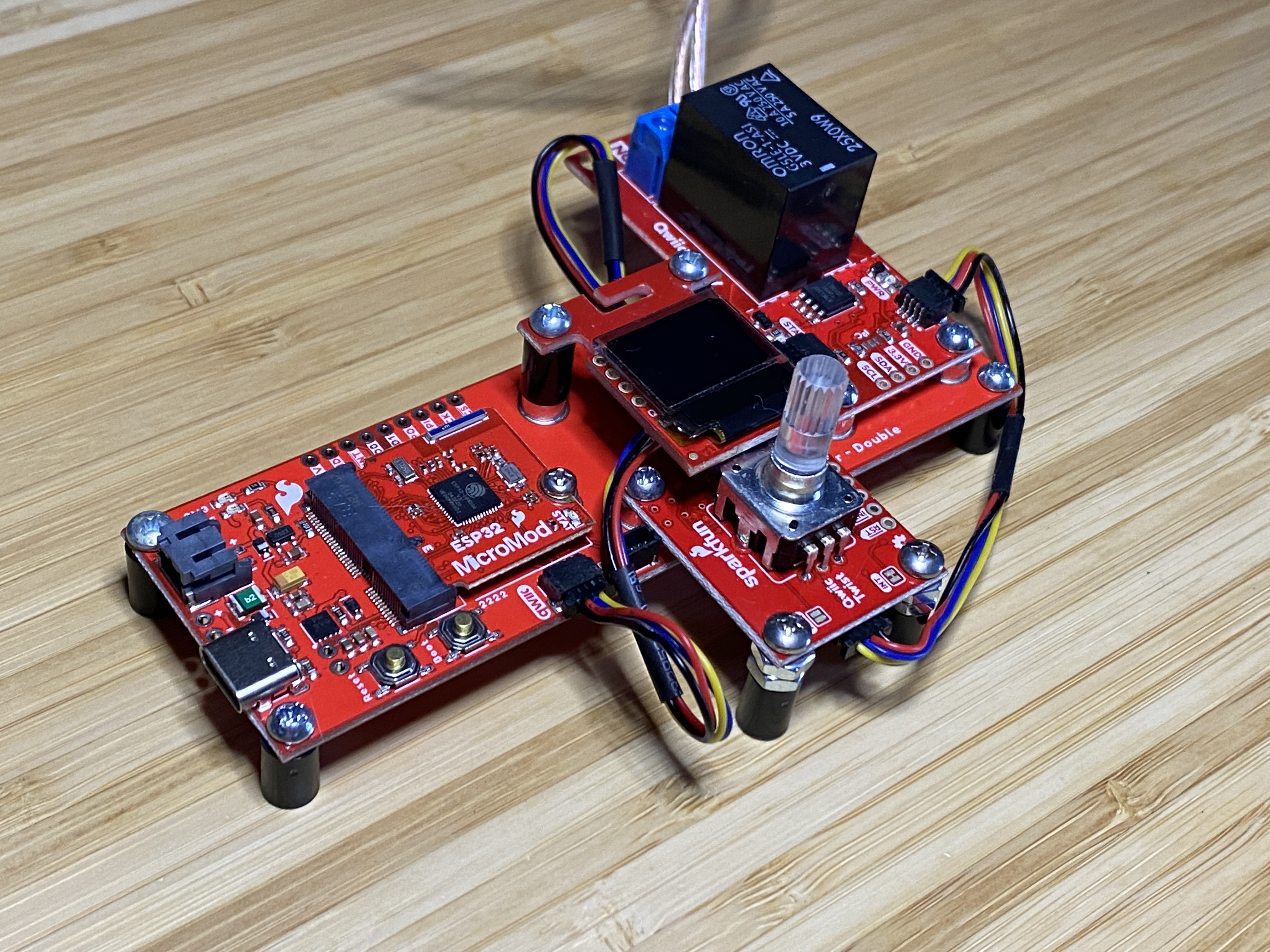
Our brand new MicroMod Qwiic Carrier boards are a few of my favourite products because they permit you to build standalone devices without irritating headers, breadboards, protoboards, jumper wires, or other mounting apparatus. And of course that in the event you opt to modify microprocessors, you do not need to do surgery on your own endeavor – simply unscrew and switch from the MicroMod chips.
To construct the control, I inserted the ESP32 chip and connected with my Qwiic Twist into the carrier to ensure its fresh mounting holes overhang that the”base” side of this carrier, using screws and also a few excess hardware to make additional supports to it. NextI used a few nylon standoffs plus a few more screws to mount my own OLED screen over the rotary encoder. This can be a tiny tricky match but it functions. I then used the residual mounting area onto the carrier board to encourage my Qwiic Single Relay and inserted a few nylon standoffs into the carrier board to let it sit on the desk.
The last step in constructing the timer will be to link everything together with Qwiic wires, and cable up the female and male barrel jacks into the relay at the”normally open” (NO) and COM screw springs. Be certain you keep the polarity consistent between the female and male barrel jacks! The built controller should appear something like this:
Given that I already followed the setup for the ESP32 MicroMod Processor and various Qwiic breakouts (see the hookup guides), I was ready to upload my sketch and test everything out. The sketch below allows the user to select how many minutes and seconds to turn on the relay, and thus the UV lightbox.
/******************************************************************************
Micromod Timer Sketch
******************************************************************************/
#include <Wire.h> #include <SFE_MicroOLED.h> #include "SparkFun_Qwiic_Twist_Arduino_Library.h" #include "SparkFun_Qwiic_Relay.h" #define RELAY_ADDR 0x18 Qwiic_Relay relay(RELAY_ADDR); TWIST twist; #define PIN_RESET 9 #define DC_JUMPER 1 MicroOLED oled(PIN_RESET, DC_JUMPER); void setup()
{ delay(100); Wire.begin(); relay.begin(); twist.begin(); twist.setLimit(59); oled.begin(); oled.clear(ALL); oled.display(); delay(1000); oled.clear(PAGE); drawPrompt();
}
void drawPrompt(){ oled.setCursor(24,0); oled.print("MINS"); oled.setCursor(24,8); oled.print("SECS");
}
int numSelector(int lnToPrint){ int lnVal = lnToPrint; int cursorYval = ((lnVal-1)*8); int returnNum; while (twist.isClicked() == false){ int cursorNum = twist.getCount(); if (cursorNum < 10){ oled.setCursor(0, cursorYval); oled.print(" "); oled.setCursor(0,cursorYval); oled.print(cursorNum); oled.display(); returnNum = cursorNum; delay(50); }else{ oled.setCursor(0, cursorYval); oled.print(cursorNum); oled.display(); returnNum = cursorNum; delay(50); } } return returnNum; }
void loop(){ //drawPrompt(); twist.clearInterrupts(); int selectedMins = numSelector(1); oled.setCursor(0,0); oled.print(selectedMins); oled.display(); twist.clearInterrupts(); int selectedSecs = numSelector(2); oled.setCursor(0,8); oled.print(selectedSecs); oled.display(); twist.clearInterrupts(); int totalSecs = ((selectedMins *60)+selectedSecs); int remainingSecs; relay.turnRelayOn(); for (int i=0; i<=totalSecs; i++){ oled.setCursor(0,24); remainingSecs = (totalSecs-i); oled.print(" "); oled.display(); oled.setCursor(0,24); oled.print(remainingSecs); oled.display(); delay(1000); } relay.turnRelayOff(); delay(100);
}
After uploading, I first attached my lightbox assembly to the control by plugging the LED strip’s 12 V power supply into the control’s female socket jack, then plugging the control’s male barrel jack to the lightbox. The control itself is powered with a USB power bank along with also the onboard USB-C connector. To place the exposure timer, turn the rotary knob until the desired variety of seconds is attained, then click on the button to confirm your choice and repeat the procedure for the amount of moments. As soon as you click the button at the knob another time, picking the seconds, the display will click and the complete remaining moments will be counted back on the OLED screen.

To examine my installation, I attempted to expose a new test pattern onto a silkscreen, expecting to leap right into creating a few shirts. Regrettably, I believe I underexposed my emulsion since my test pattern did not hold up once I attempted to clean out the display in my shower. It appeared to be functioning initially! As of now, I have not had the time to try to burn off another silkscreen, but I am positive that when I simply prolong the exposure period from 10 minutes to possibly 20 or 30, I would get dependable results. For all those wondering, I am utilizing Ecotex LED Emulsion, that is assumed to be calibrated especially for LED vulnerability components. I checked to ensure the wavelength of my UV LEDs could impact the emulsion, so theoretically all should function.
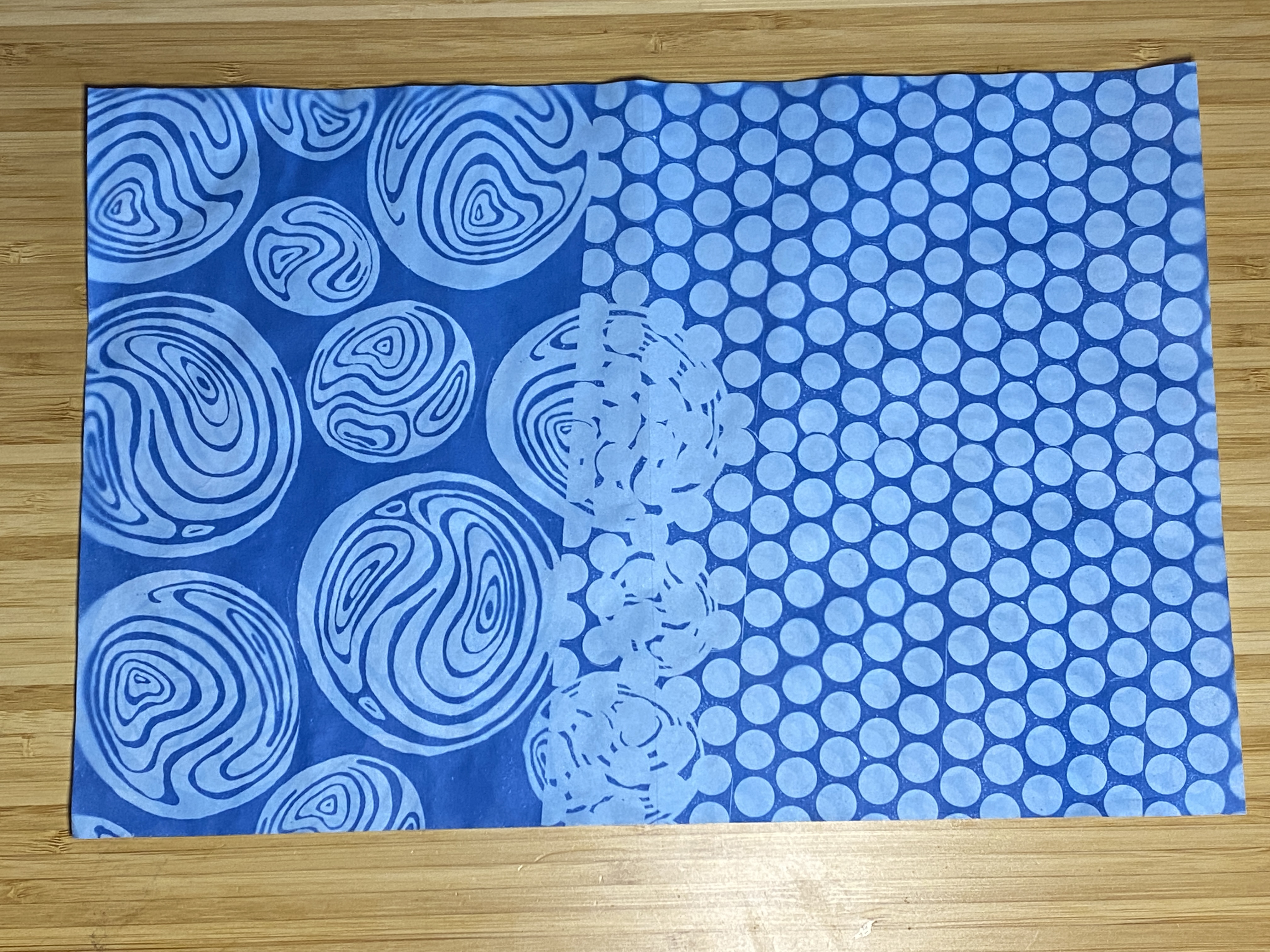
Happily, I’d have an alternate approach to try the lightbox – design newspaper! Recently in my art-making, I have been obsessed with cyanotype prints. Although kits are readily available to blend your personal materials and treat your paper, I am a huge fan of this pre-treated paper out of SunPrint kits. By playing with the time, you can really attain a selection of blue tones from light to nearly black. After exposing the newspaper, the printing is shown by submerging the newspaper in water, then washing off the unexposed areas which were shielded by the transparencies. I figure that about twenty five minutes is ideal to get dark-but-not-too-dark prints. Results under!