
Electronics are becoming smaller and smaller and the requirement to dissipate heat is constantly growing. The lack of an efficient thermal management strategy can lead to low performance, energy inefficiency, system failure, and even serious damage. With numerical simulation, such strategies can be tested early in the design process.
This article shows how to use this technology for virtual testing, with a battery pack case as an example.
Challenges in Battery Cooling
The steps in the development of a battery pack include the overall electric design, focusing on achieving the right voltage, power, and energy in balance with the life cycle, reliability, and safety. The final design must be able to withstand specific vibrational, pressure, shock, and crush loads.
In addition, the thermal design aims to maintain the cells within a given operating temperature range, in order to ensure longevity, performance, and safety. This last consideration, applied to lithium-ion (Li-ion) batteries, is the focus of the case study described in this article.
Battery Cooling: The Importance of Thermal Management
Li-ion cells and other battery types such as nickel-cadmium (Ni-Cd) and nickel metal hydride (NiMH) perform differently depending on the ambient temperature. Manufacturers usually specify 27°C as the battery operating temperature. A battery will have a higher performance at an elevated temperature, but a shortened life cycle. On the other hand, at low temperatures, the battery’s capacity rapidly decreases. For example, at -18°C, a battery could only deliver 50% of its full capacity.
Many embedded Li-ion battery packs used in high-end portable devices need to perform under challenging environmental conditions, ranging from -40°C to +80°C; military-grade sensors are a relevant example for this. In such cases, unique design strategies are required, especially to ensure sufficient cooling. Depending on the conditions, liquid cooling (which is highly efficient) or air cooling (which usually involves a mechanical component such as a fan or possibly only natural convection) is chosen.
Another important factor to consider is maintaining temperature uniformity across the battery cells, which ensures high efficiency and prevents damage.
Using Numerical Simulation for Thermal Management of Battery Packs
In battery pack design, thermal performance is traditionally assessed through physical prototyping and extensive tests.
When designing battery packs—which can be both expensive and time consuming—numerical simulation, especially computational fluid dynamics (CFD) is a complement (and for simpler cases even an alternative) to physical testing, helping reduce costs and speed up the design process. With this powerful technology being deployed as a software as a service (SaaS) application through cloud computing, designs can easily be virtually tested in a standard web browser. An additional benefit is that multiple design iterations can be tested at the same time, reaching high performance for a battery pack within minutes.
Case Study: Active Cooling Designs for Li-ion Batteries
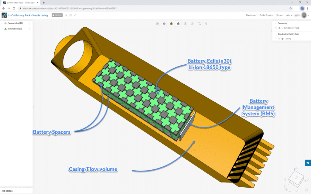
In this simulation project, a CFD thermal analysis is run to predict the temperature of 30 commercial Li-ion 18650 cells, across multiple casing designs and inlet flow conditions. The goal is to find the minimum cooling power to maintain a cell temperature below 40°C.
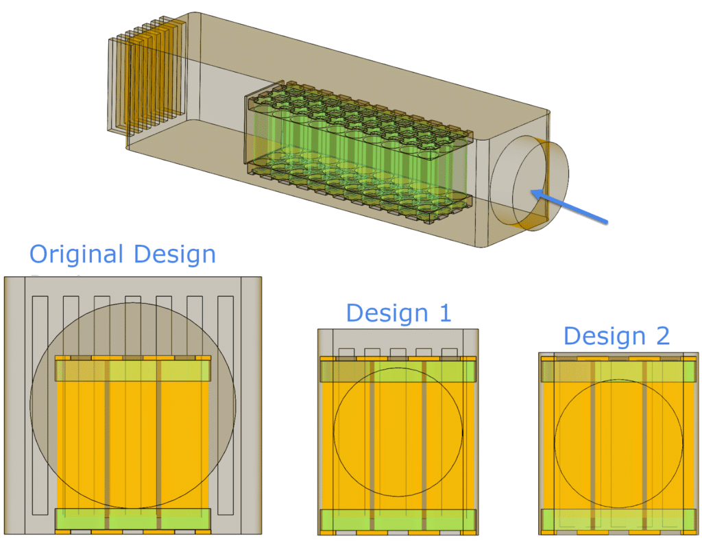
The CAD model (Source: Nilesh, GrabCAD) represents a 10s3p (10 rows of 3 cells) of Li-ion cell battery pack and a battery management system (BMS) represented by an electronics unit board. The first proposed design of the casing of this battery pack consists of an 80 mm cylindrical air intake, a straight 400 mm rectangular mid-section, and an outlet grille.
Both solid conduction and convection are modeled using the platform’s conjugate heat transfer solver. The thermal properties (conductivity, density, and specific heat) of the battery cells, the BMS board, and the battery will significantly impact the temperature distribution within the cells.
The operating conditions were assigned as a velocity and temperature at the inlet, and pressure at the outlet. Multiple air velocity values were simulated simultaneously to identify the minimum value required to maintain the cell temperature below 40°C.
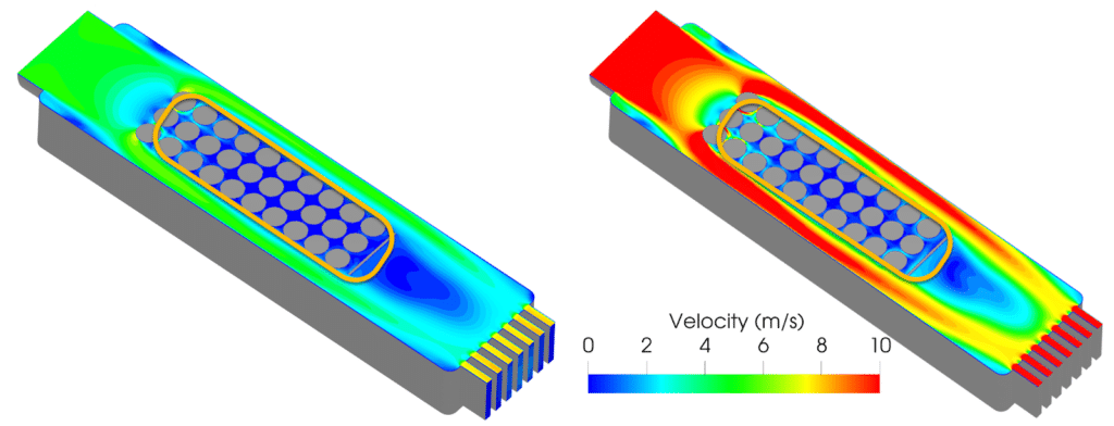
After a simulation run time of one hour, the following results were produced. With an inlet velocity of 4 m/s and shading the results by temperature, the peak value is 128°C (which means it reached 90°C above the maximum recommended temperature of 40°C).
The results indicate that either the design is poor for sufficiently cooling the cells or the inlet velocity is too low.
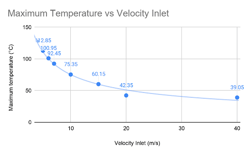
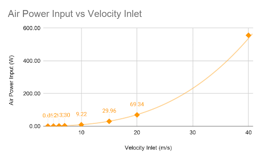
Only very high-speed inlet velocities (+35 m/s) will result in an acceptable temperature at the cell level, which could hardly be achieved by a standard fan. The second graph shows that the airpower input grows exponentially with the velocity values; hence, in order to cool down the battery pack by a couple of degrees in the higher velocity values, a large amount of power is required.
This is clear by looking at the air velocity at the midplane, with the inlet at 5 m/s, and 10 m/s.
Improved Designs for More Efficient Cooling
The simulation results showed that the central row is too hot, and a significant amount of air simply passes around the cells. Based on these insights, two new designs (Design 1 and Design 2) are proposed, with a narrower passage on the sides and upper part of the battery pack to try to funnel the air between the cells. These two designs have reduced space above the cells. The first new design has a 7.5 mm clearance, and the second design has a 7.5 mm clearance. Both have a smaller inlet diameter of 50 mm (previously 90 mm).
These new design versions can be simulated simultaneously online, using the same parameters (material and boundary conditions). Once the analysis is completed, the results are post-processed and then compared.
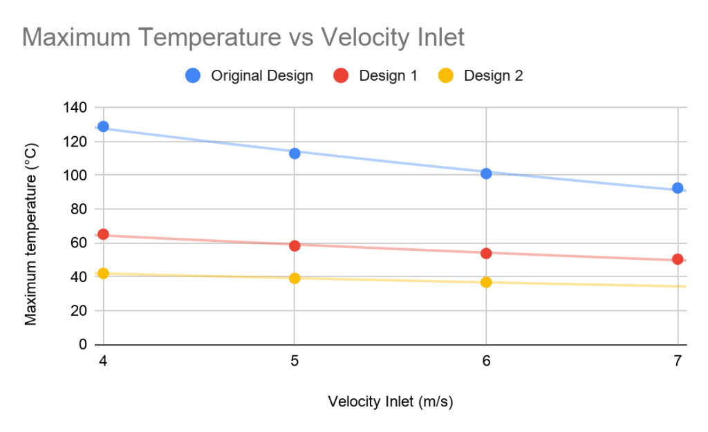
When comparing the maximum temperature of the battery packs at different inlet velocities, Design 2 (with the narrowest passage) stands out by achieving the acceptable cooling performance at an inlet velocity condition of 5 m/s. The maximum recorded temperature is 39.09°C, whereas the lowest temperature is 28.35°C.
The following chart showing a maximum temperature comparison reflects a significant difference between the original and new design. The lower the curve, the better.
The required cooling power for each design is an important factor, as reducing the air space too drastically can lead to higher power costs. A compromise must often be found.
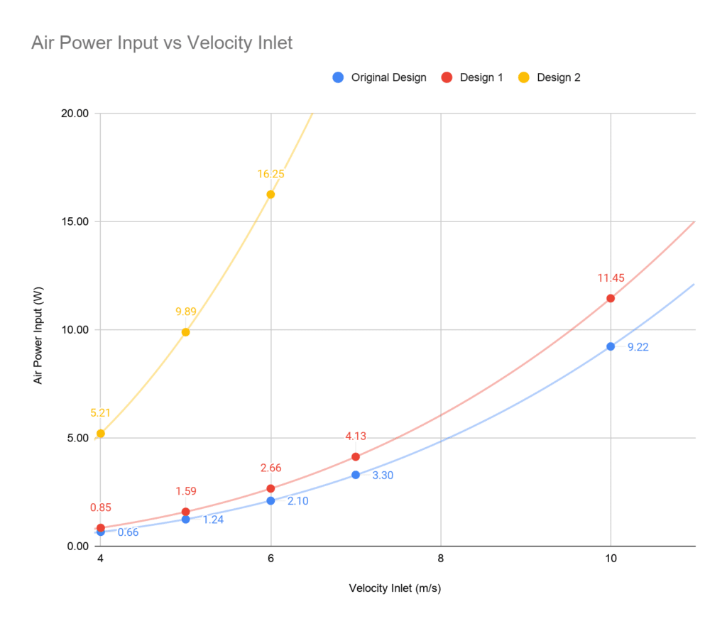
With a 5 m/s inlet, the cooling power required is about 9.81 W, which makes the fan choice very clear. In contrast, Design 1 would need 37 W to cool the battery cells to ~39°C (inlet velocity of 15 m/s).
Conclusion
Maintaining battery packs within a specific temperature range is essential in ensuring performance and safety. The cooling role of forced air at high velocity is reflected in the simulation results. Design changes, including forcing more air through the cells to facilitate heat transfer, prove to be effective.
The final design shows that a fan using 9.8 W of power at 5 m/s can efficiently cool the battery pack within the required limits. In contrast, the original design was much less energy efficient, requiring 555.96 W.