
Skin effect – a phenomenon occurring in AC circuits that causes the current density near the surface of a conductor to be greater than inside it. Skin effect increases the effective AC resistance of the conductor, causing an increase in power losses in the conductor. The value characterizing the skin effect is the penetration depth (of magnetic field or current into the conductor). This quantity depends on resistivity, magnetic permeability of the medium and frequency of the current.
Skin effect results from the interaction of a magnetic field and an electric field. Alternating current flowing in a conductor creates an alternating magnetic field. This field induces an alternating, oppositely directed electric field. This in turn causes secondary currents, flowing in the conductor in the opposite direction of the primary current. These currents reduce both the magnetic field strength and the local current density. Since the strongest electric field is induced inside the wire, this is also where the current disappears most strongly.
Skin effect can also be explained by the principle of so-called magnetic diffusion defined by Maxwell’s equations. A current in a wire creates a magnetic field around itself. Since this field is time-varying, it enters the conductor as an electromagnetic wave and is attenuated due to the lossiness of the medium. At the surface of the conductor, currents are induced that add to the source current, while inside the conductor, the source current is reduced by them. If the thickness of the conductor is large and the frequency is high (the electromagnetic wave then has a small length), a situation may occur when the currents coming from the magnetic field are summed larger than the source current and then inside the conductor a current starts to flow in the opposite direction, which is a very unfavorable phenomenon.
Consider a cylindrical wire of radius a and infinite length. A current I = I0 cos ωt flows through the wire. For not very large frequencies ω we can neglect the displacement current, which is equivalent to neglecting the effect of radiating energy through the wire in the form of an electromagnetic wave. The current density and the electric and magnetic field strengths are written in complex form, with harmonic dependence on time

Faraday’s and Ampere’s laws for the fields inside the wire are:

where σ – specific conductivity, μ – relative magnetic permeability of the wire material. For rotation in cylindrical coordinates the following formulas are valid:

Assuming that the wire is directed along the z-axis, equations (1) in the cylindrical system can be written as:

where H = Hφ, E = Ez. By differentiating the second equation (3) after r, we can write the differential equation for the electric field strength

marking
where


results in:

Introducing the variable x = qr we obtain the equation

This is a Bessel equation of zero order. Its general solution is the linear combination of Bessel functions of the first and second kind A J0(x) + B Y0(x). We must discard the Bessel function of the second kind Y0 because Y0(0) = ∞. The electric field on the axis of the wire, for r = 0, cannot be infinitely large. The electric field inside the wire is therefore

where C = const. Using the second of equations (3) we can calculate the magnetic field strength inside the wire

Using the formula for the derivative of the Bessel function
results in

From equations (3), one can verify that the differential equation for H is indeed a Bessel equation of order 1. According to the integral version of Ampere’s law, the value of the magnetic field strength at the surface of the wire should be

Hence the integration constant C is

Finally, the electric and magnetic field strengths inside the wire are

According to Ohm’s differential law, the current density inside the wire is

The ratio of the current density inside the conductor to the current density on its surface, for r = a

The absolute value of the current density | j(r)| inside the wire, relative to its value | j(a)| on the surface

where ξ = r/a < 1. We are dealing with Bessel functions from a composite argument, which physically means that at different distances from the wire axis the time dependence of the current density is phase shifted. In the argument of the Bessel function there is a dimensionless constant
dependent on the conductor radius a, the current frequency ω, and the material constants σ and μ of the metal from which the conductor is made.
Figure 1 shows the absolute value of the ratio of the current density inside the wire to its value on the surface, for several selected values of the parameter ka. It can be seen that for sufficiently high values of ka, the current flows practically entirely on the surface of the conductor. This effect is called the skin effect.
The table below shows values of the ka parameter for a conductor with a diameter of 1 mm, for selected current frequencies. For copper σ = 5.8 – 10^7 S/m, for steel σ = 1.0 – 10^7 S/m, μ = 1000.
| f | 50 Hz | 10 kHz | 100 MHz |
| Copper | 0,08 | 1 | 100 |
| Steel | 1 | 14 | 1400 |
The skin effect is of great practical importance in electrical engineering. For high-frequency currents, the resistance of a conductor comes entirely from the thin layer of material on the surface. Since copper and aluminum, from which electrical conductors are made, tend to oxidize, this resistance can be much greater than the specific conductivity value of the pure metal would suggest. It may also be noted that most of the metal inside the wire does not participate at all in the transmission of electric current, and that increasing the diameter of the wire does not lead to a decrease in resistance. For high-frequency currents, therefore, a braided wire consisting of many thin conductors is often used.
Skin effect in a finite thickness conductor
Consider an infinite layer of conductor with thickness d = 2a. Let us assume that on both surfaces of the layer a homogeneous harmonic magnetic field of strength H0 is given, parallel to the surface of the layer. Such a field configuration exists in the core of a transformer consisting of many layers of insulated thin steel sheet.

If the transformer core were made from a single thick piece of conductor, large eddy currents induced by a time-varying magnetic field would flow in the cross-section of the core, and thus large Joule Lenz heat would be emitted in the core. Inside the conductor, Faraday’s law applies:

and Amper’s law:

The density of current induced in a conductor is related to the electric field strength:

Where σ – specific conductivity. Material equations:


Let’s write Faraday’s and Ampere’s law in Cartesian terms. If the conductor is infinite in the x and y directions, then the fields can only depend on the variablez. For large intrinsic conductivity σ and small field frequency ω, we can neglect the shift current in Amper’s law. For harmonic fields, we replace the derivative after time by the factor iω.


The electric field and the current density inside the conductor are directed along the x-axis. Thus the magnetic field inside the conductor satisfies the following differential equation

where the complex constant
where
The root of the imaginary number is:
The general solution of the differential equation (5) is a linear combination of exponential functions:

The magnetic field at the layer surface for z = -a and z = a must satisfy the following boundary condition:

Hence the integration constants are:

The solution of equation (5) satisfying the boundary conditions (7) is of the form:

Based on equation (4), we can also give an expression for the induced current density in the layer is:

The current density induced at the layer surface for z = a is

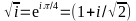
It is easy to see that jx(-z) = – jx(z), so at the center of the layer the current does not flow, and at the surface z = -a it has the opposite direction than at the surface z = a. By introducing the following dimensionless notations: ξ = z/a, β = ba we can write an expression for the modulus of the current density related to the value at the surface of the layer:

The distribution of current density in the cross section of the conductor according to equation (12)
As can be seen from figure (1), for the value of dimensionless parameter β > 3 there appears a skin effect – the current starts to flow mainly near the surface of the conductor. To calculate equation (12) we need expressions for hyperbolic functions from the complex argument:

and their modules

In a similar way, we can write the expression for the modulus of magnetic induction related to its value at the surface of the layer:

Let the frequency of the external magnetic field be f = 50 Hz. The magnetic steel has a specific conductivity equal to σ = 10^7 S/m, and its relative magnetic permeability is μ = 1000. The parameter b is then equal to 1.4 mm-1. The depth of field penetration into the conductor λ = 2π/b is about 5 mm. The following table shows the dependence of the dimensionless parameter β appearing in equations (12) and (15) as a function of film thickness:

Skin Depth
One of the quantities important in eddy current testing is the equivalent penetration depth of the electromagnetic field δ (also called standard penetration depth or simply penetration depth). This quantity conventionally defines the thickness of the material layer under test. The current density induced in a semi-infinite conducting plate by a sinusoidal time-varying plane electromagnetic wave penetrating it varies exponentially with distance from the surface. The value of this density for a particular depth z depends on the frequency f and the material parameters of the plate. Assuming that in a Cartesian coordinate system whose z-axis is perpendicular to the plate surface, the magnetic field strength vector has only a tangential component to the surface, the current density also has only a tangential component to the surface. The modulus of the current density varies according to the relation:

Where J0 is the modulus of the current density at the surface of the object.
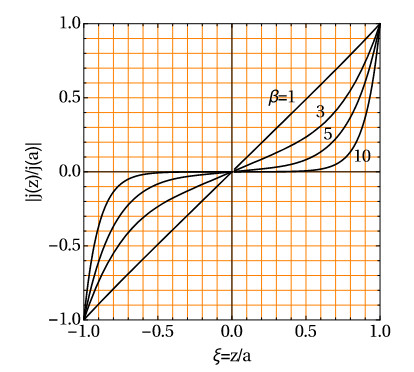
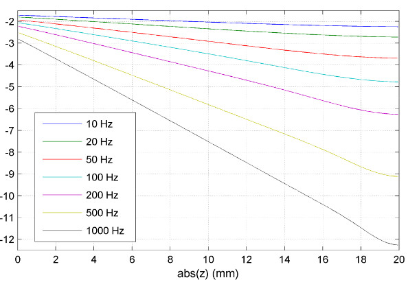
Figure 3 shows graphs of eddy current density values induced in a copper plate by a three-winding flat coil energized at frequencies of 10, 20, 50, 100, 200, 500, and 1000 Hz. The graphs show the absolute values of the currents along the z-axis from the surface (0 mm) to the bottom of the plate (20 mm), for the coordinate r = 20 mm (position of the central coil). The highest values of the current density induced on the surface occur for the highest of the adopted frequencies (black line). At the same time, for this frequency, the values of current decrease most rapidly along the depth of the plate, taking values close to zero at its bottom surface.
Fig. 3 Current density modulus |Jφ| (A/m2) induced in a copper plate by a three-winding coil energized at frequencies from 10 Hz (blue line) to 1 kHz (black line). Calculation results from Comsol Multiphysics program.
Basis:

The expression for the current density can be represented as:

It can be seen that δ is the depth at which the amplitude of the current density decreases e-fold. The penetration depth δ can also be thought of as the thickness of the layer in which the total current of constant density is induced, and beyond which no current is induced at all. The value of the penetration depth δ depends on the frequency of the field and on the magnetic permeability and electrical conductivity of the material under consideration. An effective penetration depth of 3δ is also determined, at which the induced currents decrease below 5% of the value of the current density at the surface. At the same time, as the amplitude of the current density decreases, the phase delay angle of the current with respect to the current at the surface increases. The value of this angle (in radians) is:

Figure 4 shows the phase delay angle of the induced current (in radians).
coil energized at frequencies from 10 Hz (blue line) to 1 kHz (black line).
Calculation results from Comsol Multiphysics program.
References:
http://www.if.pw.edu.pl/~wierzba/zajecia/ed15/skin_ef/tekst.pdf
http://www.if.pw.edu.pl/~wierzba/zajecia/ed15/2016/skinef1.pdf
https://ks.zut.edu.pl/pliki/EM7_PrzetwornikEC.pdf