
CAN Protocol
CAN bus protocol which is also known as control area network protocol is a half-duplex high-speed serial network technology developed by Bosch in the 80’s. This protocol is mainly used in automobile industry to communicate between various network devices in a low radius region to reduce the cable wiring. This protocol is designed for robust and flexible performance in harsh environments and applications such as lighting control, central locking, engine management systems etc. A CAN protocol is also a collision detection arbitration on message priority protocol which ensures each node on the network must wait for a given period before sending any message.

CAN Architecture
CAN is using an open systems interconnection model to transfer data among nodes connected in a network. This model consists of several layers through which the data is passed during the communication between devices connected in a network. Every layer has a specific function that supports the layer as described below. Application layer: It acts as a window for users and application processes to enter to the network services and interacts with the application/operating system of the CAN device.
- Presentation layer: This layer defines data formats and act as a data translator, which is used by the application layer at the receiving end of the station
- Session layer: It controls the establishment, communication and termination of the sessions between processes running on two different devices connected to the network performing security, name recognition and logging.
- Transport layer: This layer makes sure that the messages are delivered without any errors, in proper sequence, and without loss.
- Network layer: This layer provides end to end logical addressing system. Therefore, a packet of data can be routed through many layers and establishes, which connects and terminates the network connections.
- Data link layer: This layer packages and converts raw data into frames transferred from the physical layer. It transfers frames from one device to another without any errors. This layer has two sub layers called Medium Access Control Layer and Logic Link Control Layer.
- Physical layer: This layer transmits bit from one device in the network to another and controls the transmission of bit streams
CAN protocol uses only two layers of the open systems interconnection model. The other layers can be used according to optimize the design according to the needs of the system designers. Every node in the CAN bus requires the following.
- Transceiver: Transceiver converts the data from the CAN controller to CAN bus levels and also converts the data from CAN bus levels to suitable level that the CAN controller uses.
- CAN controller: They handles network functions such as framing, CRC and act as an integral part of the microcontroller CRC etc.
- Microcontroller: This takes care about what the received messages mean and what messages it wants to transmit.

CAN Bus frame
Communication on CAN protocol is done using messages which are sent in a format called as frames. This message is a pre-defined structure which carries meaningful sequence of bit or bytes of data within the network. Framing of message is done in the Data Link Layer. CAN protocol uses a multi-master bus, where all messages are broadcast on the entire network? The identifiers in the CAN bus frame provide a message priority for arbitration. Standard CAN frame with bit identifier is shown in the below diagram.
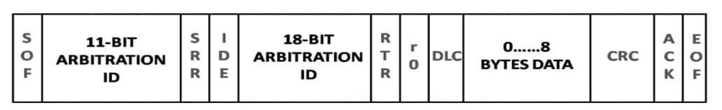
Per definition a CAN data or remote frame consists of the following sections:
- SoF (Start of Frame): This bit indicates the beginning of a message with a dominant (logic 0) bit
- Arbitration ID– This identifies the message and indicates the message’s priority. There are two formats standard and extended, which uses a 11bit and 29-bit arbitration ID respectively.
- IDE (Identifier Extension) – Differentiation between the standard and the extended frames is allowed by this bit
- RTR (Remote Transmission Request) – Differentiation of a remote frame from a data frame is done by this bit.
- DLC (Data length code)– This specifies how much bytes that the data field contains
- Data Field– contains up to 8 bytes of data and up to 64 bytes of data for CAN-FD (Flexible Data rate)
- CRC (Cyclic Redundancy Check)– This field is for detecting errors.
- ACK (Acknowledgement slot) – When the CAN controller correctly receives a message it sends an ACK bit at the end of the message. If there is no ACK, the transmitting node checks for the presence of the ACK bit on the bus and reattempts transmission.
CAN bus protocol communication
CAN is a peer to peer network, there is no master to control the transmission between nodes. When a node in CAN is ready to transmit data, it usually undergoes through a process called message arbitration. In the message arbitration process, CAN node will check to see if the bus is idle and initiates the transmission once the bus is idle. This action triggers the other CAN nodes in the bus and results in two or more nodes starting a message at a same time which results in a conflict in the network. It can be resolved by following methods,
- Transmitting node checks the bus while they are sending data
- If any node in the network detects a dominant level (logical 0) when sending a recessive level itself, it will fail in the arbitration process and quits immediately will start acting as a receiver.
- This arbitration process is performed while sending the arbitration ID field of the CAN frame and at the end, only one transmitter is left on the bus i.e. the node with the highest priority (lowest arbitration ID) will pass the arbitration.
- After that, the node which has won the arbitration will continue message transmission as if nothing had happened.
- Other receiving node can decide if a message is relevant or if it should be filtered using a combination of hardware and software filters.
- This is a continuous process and other nodes will transmit their messages when the bus has become available.
CAN Bus signal
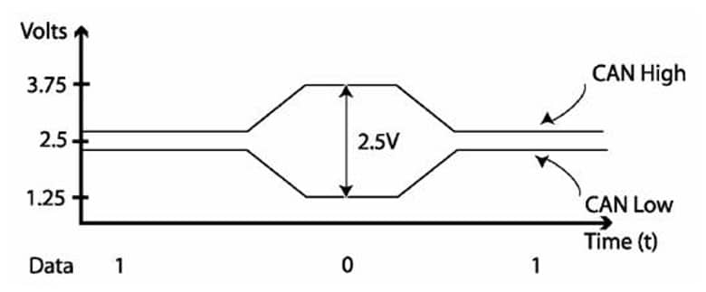
In the idle mode of CAN bus, the two lines carry 2.5V. During the data bit transmission, the CAN high line goes to 3.75V and the CAN low drops to 1.25V, thereby generating a 2.5V differential between the both lines. CAN bus is not sensitive to inductive spikes or other noise because its communication relies on a voltage differential between the two bus lines.
Power to the CAN system can be supplied through the same bus or using a separate power supply. All modules in the CAN network can transmit and receive data. Usually a CAN network operates at a bus speed of 250 kB/s or 500 kB/s depending on the system. In the present in some vehicles they use up to 3 separate CAN networks, having different speeds and connected by gateways. Normally the data on one of the networks is also available to the remaining networks. As an example, take engine management function, chassis system and local interconnected bus. They are working in 3 separate bus speeds 500 kB/s, 250 kB/s and lower speeds respectively.
Advantages and disadvantages of CAN bus
Following are some pros and cons of CAN bus over other bus types.
| Advantages | Disadvantages |
| Low use of wiring due to its distributed control | Limited length |
| Can be applied to many electrical environments without any issues. | Network must be wired in topology that limits stubs as much as possible. |
| Multi master and multicast features can be applied | Undesirable interaction between nodes |
| High speed data rate | Limited number of nodes (up to 64 nodes) |
| Low cost and light in weight and robustness | High cost for software development and maintenance |
| Supports auto retransmission for attribution lost messages | Possibility of signal integrity issues |
| Built in error detection capabilities. (ack error, form error stuff error etc.) |
Devices with CAN bus connection
Arduino don’t have any inbuilt ports for CAN bus, so we have to use a CAN module interfaced with Arduino. Usually these modules communicate with Arduino using SPI communication method. In the following example we have used two MCP2515 high speed CAN transceivers to send humidity and temperature data to Arduino Uno from Arduino Nano. Users have to install a separate library for CAN to easily interface with MCP2515 CAN module.

In the past the CAN sensors were connected indirectly to the CAN networks via I/O modules but in the present, there are modules developed inbuilt integrated CAN interfaces which avoids cost intensive I/O or gateway modules. These sensors support higher layer protocols such as CANopen, J1939 or DeviceNet depending on the application field. There are also integrated CAN interface sensors that do not support any standardized higher layer protocols and they can be directly connected to the CAN bus lines.